Low Cost Electronic Drums
| Return to Alan's Kit | Return to Main Page |
Hey all you head bangers out there!! Have you visited your local music instrument store lately and checked out the prices of commercial Electronic Drum kits? That's right, $THOUSANDS$, correct? Being of the lower income drummer class and knowing Alan (the fine gentleman who runs this site) we desired a lower cost solution for the ever prevalent and sometimes controversial subject "Drums in Church!" Controlling the sound of an acoustic kit can be somewhat cumbersome in a venue such as a church sanctuary where acoustics can run wild. We decided to go with an electronic kit where we had total control over the volume and sound projection.
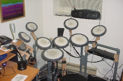
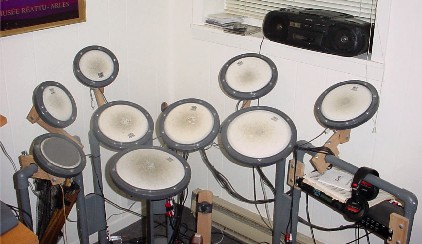
Alan had already built a fine kit for his home studio described elsewhere in this site. We wanted to take it a step further so I decided to experiment with using REMO practice pads as the pickup heads since they have real drum heads and realistic drum response. After experimenting with various piezo transducer mounting configurations, I finally settled on the stack up described here. From there I took Alan's mount design, modified it to hold the pads as well as the Drum Module (Alesis D4) and Wa La!! We had a kit suitable for use in our church's Sanctuary. We noticed that there is at least one other site out there describing the use of REMO pads in the construction of an electronic kit. We are publishing our process as another alternative to high priced kits. Just as a teaser, here is the first finished kit in my basement along with other irrelevant items. The total cost was around $500 including the Alesis D4.
Ready? Here we go!!
Pad Design
I Started with REMO practice pads and used all 3 sizes (6, 8 and 10 inch) to give the kit a look closer to an acoustic kit. However, you may use whichever size(s) whets your whistle. The stack up is the same. I used 10 inch pads for the snare and "Floor Tom", 8 inch for two tenor toms and ride and right crash and 6 inch for the left crash, high hat, and aux pad. The kick is just a wooden frame utilizing a rubber pad with a transducer behind it struck with my DW 5000 pedal. Piece of Cake!!
Materials
The materials used to modify the pads were obtained from the vendors listed next to the item.
1. REMO Practice Pads - REMO
2. RCA Jack, panel mount - All Electronics
3. Piezo Transducer - All Electronics - They have various. The ones I used are ~ 1 inch in diameter with two 6 inch leads. Cost ~ $1 each. Buy a bunch. They do wear out, leads break off, etc.
4. Galvanized or other metal sheet - Home Depot - This is for cutting the transducer mounting board. You can use hard plastic or even thin wood. Metal seems to give good response and dynamic range for the pad.
5. Felt or thin foam (1/8 inch). This is inserted between the pad head and the mounting board. It prevents the transducer from being struck directly. I used one circle of each.
6. Contact cement or other glue suitable for metal to metal bonding.
7. The material required for the kit frame construction is described later.
Tools
1. Drill (1/4" and 1/8" bits)
2. Solder Iron and Rosin Core (60/40) Solder
3. Small wrench
Pad Stack Up
Figure 1 is a cut away of the stackup.
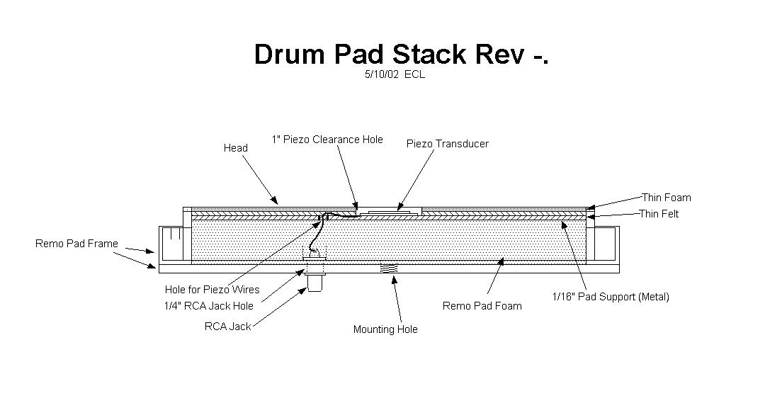
Figure 1. Drumpad Stackup
Instructions
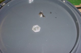
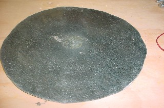
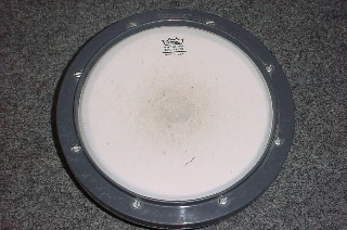
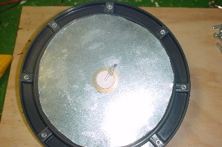
1. Disassemble the REMO pad, removing all of the screws, retainer ring, head, head film and gray foam.
2. Drill a 1/4 inch hole between the spoked ribs of the pad base 1/3 of the way from the pad center to the outer edge. Mount the RCA jack thru the hole with the lugs on the inside of the pad.
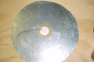
3. Poke a hole through the gray foam in approx. the same position as the RCA jack. The wires from the piezo will be inserted through this hole. 4. Cut a circle of the material you have for the piezo mounting board (sheet metal is shown in these pictures) slightly less than the diameter of the inside of the plastic base. Drill a 1/8 inch hole in the same position as the hole in the foam pad. Hopefully your circles are better than mine. 5. Using steel wool, roughen the center of the mounting board and the bottom of the piezo. Using contact cement, mount the piezo transducer directly to the center of the board with the wires pointed toward the previously drilled hole. The piezo in this picture actually has 3 wires. The red and blue wires are connected to the same lug (center) on the RCA jack. Insert the wires through the hole in the board. If metal, dab a small amount of glue in the hole to serve as a grommet to prevent chaffing.
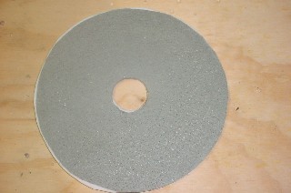
6. Cut circles out of the felt or thin foam, two per pad. I used one of each. Cut a small hole ~ 1 inch in diameter in the center. This will prevent any direct striking of the piezo transducer which might crack the crystal. It also increases the dynamic range of the transducer.
7. Feed the transducer wires through the thick foam. Position the stack to allow connection of the wires to the RCA jack. The Red wire will attach to the center conductor and the black to the outer. Solder the wires. Lay the foam and board into the bottom tray, piezo side up of course and the RCA jack poking part way through the hole in the foam.
8. Place the thin Felt/foam circles on top of the board.
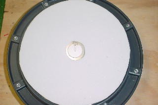
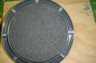
9. Install the head film and head over the stack. Place the ring over the edge of the head and insert the screws. Tighten opposite screws until the head is tensioned quite tight. One pad complete!!
You will require a drum module (Alesis D4, DM5, . . .) to test the pad and to create the drum sounds for the rest of the kit. I picked up a couple of used D4s for under $200 each. They may even be cheaper now. Repeat the process for each pad. Since all pads have nearly identical configuration, setup of the triggers (sensitivity, dynamic range, attack, crosstalk, etc.) on the drum module should be almost identical for all trigger inputs.
The Kick
As stated before, the kick trigger is a simple mechanism. A standard pedal is used (a DW5000 is shown in the pictures) and it is mounted on a board with another wooden arm at right angles holding the strike pad and Piezo. It actually has a very good dynamic range and control. I used 1 x 3 oak boards to construct the kick frame. The floor board is ~ 8 x 14. Secure the vertical board to the end of the floor board. I used a hinge on this one so it can be easily folded for travel. Make sure it cannot move past vertical. Position the pedal on the floor board so the beater strikes the vertical board about where it would strike an actual bass drum head. Mark and drill two holes where the pedal spikes would normally anchor the pedal to the floor. Mark where the beater strikes the vertical. On the front of the vertical, using a wood bit of ~ 1 1/4" diameter, drill a hole 1/2 way through the board at the location of the mark. The point of the bit should be through the back of the board. This is where the piezo wires will be run. Using contact cement, secure the piezo in the bottom of the hole you just drilled, feeding the wires through the small hole to the back of the board. Cut several disks of felt ~ 2" in diameter. These will be placed over the hole and the beater will strike this felt. I found a rubber pad (1/4" thick) and used that also to give some bounce feel to the pedal. Secure the felt/rubber circles to the vertical. I cut an old bicycle tube, making a thick band, sliding it over the pads and the board. This holds things in place very well. To mount the RCA jack, take a small metal angle and drill out one of the screw holes to 1/4". Insert the RCA jack and install washer and nut. Tighten. Mount the angle with the RCA jack just below the hole with the jack facing down. Solder the red wire coming through the hole in the vertical to the center lug of the jack and the black wire to the ring lug. One home made kick ready for some serious hammering!!

Constructing the Kit!
You are now ready to build the base and frame for holding the pads. This involves some basic woodwork and PVC pipe cutting/gluing and that is about it. Nothing fancy here. (There is additional information as well as some pictures on Alan's other drumset page). As shown, this kit is built from PVC pipe (painted) and oak boards. There are 8 legs and 4 horizontal bars for mounting the pad arms. The snare is mounted on a standard snare stand with the top removed. The D4 mounts under the right most bar between the legs. All of the pieces should be fabricated before assembly begins.
| Return to Alan's Kit | Return to Main Page |